


This week’s blog is another addition to our valve adjustment series. By the end of this series, we aim to cover every Honda engine series and demonstrate how to perform a valve adjustment on each one. This week, our focus is on the K20A engines!
In this post, I’ll be tackling two valve adjustments simultaneously. If you’ve been following the blog, you might recall the articles about my brother’s EG equipped with a K20A engine. Since his car is nearing completion (again), I want to ensure everything is within spec before sending it back to him.
If you’d like to catch up on the journey of his car, you can find links to the previous articles below.
When it comes to doing a valve adjustment on my car, it’s something I take seriously. I push my car pretty hard, so keeping it in top shape is a priority for me. That’s why I stick to a maintenance schedule of every few months instead of waiting years.
That said, I genuinely enjoy the process. There’s something really satisfying about pulling off the valve cover and making those precise adjustments. It’s more than just maintenance—it’s time I get to spend in the garage doing something I love.
For this post, I thought it’d be interesting to cover both cars at the same time. It’s a nice way to mix things up and make the write-up more engaging than just focusing on one car.
Before we dive in, let me quickly give new readers some backstory about our K20s. We purchased them together about four years ago from HMO (Honda Motors Online). Both swaps are JDM DC5 K20A engines, upgraded with just bolt-ons.
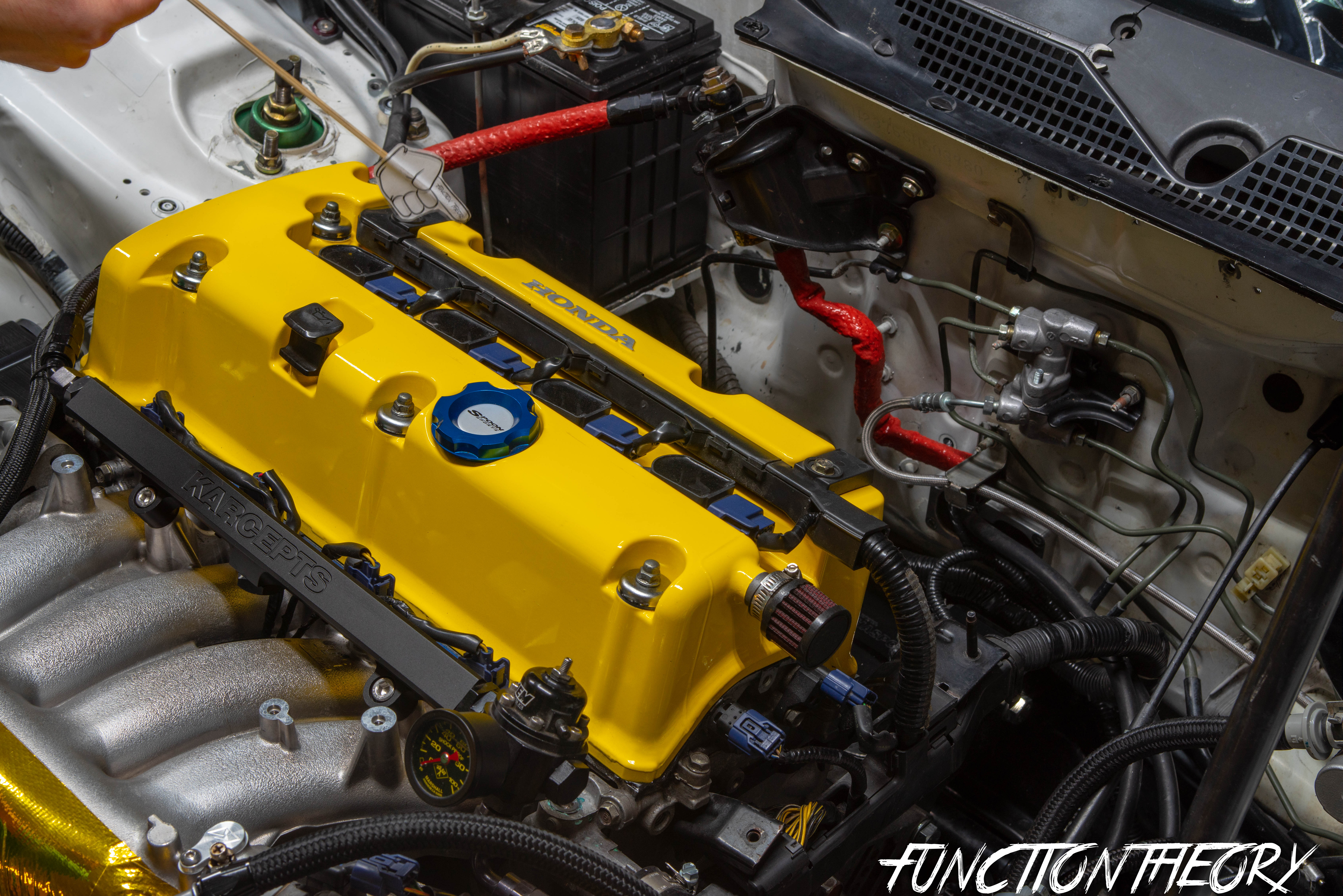
As you can see in the valve train picture below, these engines are incredibly clean, which is why I always recommend getting swaps from HMO. Eric’s car has traveled across the U.S. four times, and mine has endured countless hard miles on the track. Despite that, both engines have held up beautifully.
These are essentially stock DC5 swaps with a tune, retaining that legendary OEM reliability. With regular maintenance, they can last for many years, which brings us to the purpose of this post—a step-by-step guide to performing a valve adjustment.
Let’s start by clearing a few things up. Unlike the B-series engines, there are a few different styles of K-series engines. If you’re working with something other than a K20A, K20Z3, or K20Z1, the process might differ slightly. That said, the general motions are the same—you’ll just need to look up the specific valve adjustment specs for your engine.
You’ll also notice that my engine isn’t in a Civic Si or RSX Type S. If you’re working on one of those, you may need to remove a few extra components, like the plastic intake manifold cover, vacuum lines connecting the intake to the valve cover, and possibly other bits. Those should be straightforward enough to figure out, so I won’t go into detail about removing them here.
Here are the tools I used for this job. Keep in mind that you might need additional tools depending on the specific components you have to remove.
- 10mm socket: For the valve cover bolts, coil pack bolts, and ground bolts/nuts.
- 19mm socket: For the crank pulley bolt, which you’ll use to turn the engine manually.
- Spark plug socket and long extension: To remove the spark plugs.
- Ratchet: For general use.
- Jam nut valve adjustment tool: For adjusting the valves.
- Feeler gauges: To measure valve clearance.
- Magnet: Handy for retrieving dropped parts.
- Breaker bar: For extra leverage, especially on the crank pulley bolt.
- Rag: To clean surfaces and catch spills.
- Hondabond: For resealing the valve cover.


The most important tool for making this job easier is the jam nut valve adjustment tool. Some people claim you can get by with a 10mm closed-end wrench and a flathead screwdriver (which is essentially what the jam nut tool combines), and while that might work, using the proper tool saves you a lot of frustration.
Another helpful item is a set of angled feeler gauges. They make the process significantly smoother and more convenient.

You’ll also notice a few other tools in the picture. I used these because I had to snip some zip ties and remove my strut bar as part of the process.
Step 1:
Start by breaking the front right wheel loose. Then jack up the front of the car and secure it on jack stands. Remove the wheel to gain access to the 19mm crankshaft pulley bolt.
(If you’d prefer not to jack the car up, you could turn the wheels fully to the right and sneak a ratchet in that way. However, in keeping with our “low frustration” approach, removing the wheel makes the job much easier and more straightforward.)


Once the wheel is removed, you’ll have easy access to the 19mm crank pulley bolt. To make the process a bit easier, I use a 19mm socket paired with a 3/4 ratchet, which helps with smoother and more efficient turning.


I’ll leave the ratchet on throughout the entire valve adjustment process because you’ll need to manually turn the engine to TDC (Top Dead Center) for each cylinder.
JUST DON’T FORGET TO REMOVE IT BEFORE YOU START THE CAR!
SERIOUSLY!

Step 2:
Removing the valve cover: As I mentioned earlier, your car might have additional plastic components that mine doesn’t, but I’m not going to cover how to remove those. They should all come off with a 10mm socket anyway.
Since I don’t have a spark plug wire cover, I’ll jump straight to removing the 10mm nuts holding the valve cover in place. There are six in total that need to be removed.
One.
Two.
Three.
Four.
Five.
Six.
Next, remove the two 10mm bolts holding the coil pack harness. (Your setup might differ—yours could have 10mm nuts on studs instead of bolts.)
One.

Two.

Now, remove the 10mm bolts securing each coil pack to the valve cover.
Cylinder #4.

Cylinder #3.

Cylinder #2.

Cylinder #1.

Remove the 10mm ground wire bolt.

Now, one at a time, lift the coil packs enough to unclip the plug. Be careful not to pull too hard on the coil pack harness.

Bing,

Bang,

BOOM!

Next, carefully move the coil pack harness back toward the firewall. Your valve cover should look similar to mine now. I forgot to mention earlier that you’ll also need to remove the dipstick.
Notice that I’ve removed all the bolts but left the grommet washers in place. In the next step, I’ll show you how to remove them without losing or having them fly off. (Yes, that’s a chip in my genuine Spoon valve cover.)

Now, I’ll show you how to remove those washers without losing them. Use the magnet I mentioned earlier to carefully remove each washer one by one. You can leave the rubber grommets in place—they should stay in the valve cover as you remove it. Just be cautious and pay attention to ensure none of them get lost.
If your valve cover grommets and washers are old, this would be a great time to replace them. I’ll be reusing mine since they’re relatively new.

I removed the spark plugs for two main reasons. First, it allows me to inspect them and check how the engine is running. Second, removing the spark plugs makes it much easier to rotate the engine using the ratchet on the crank pulley since compression won’t build in the cylinders.
Technically, you don’t have to remove the spark plugs, but removing them helps minimize potential frustration. It also makes it easier to line up the timing marks on the gears, as compression won’t push the piston back down slightly when the engine reaches TDC.
(Be sure to remove all 4 spark plugs.)


Now, remove the valve cover. It may be stuck on there pretty tightly, especially if your valve cover hasn’t been off the engine in over 100,000 miles.
DO NOT use any metal tools to pry between the valve cover and the head. Doing so can easily scar/mare the head where the valve cover gasket seals, potentially causing persistent leaks.
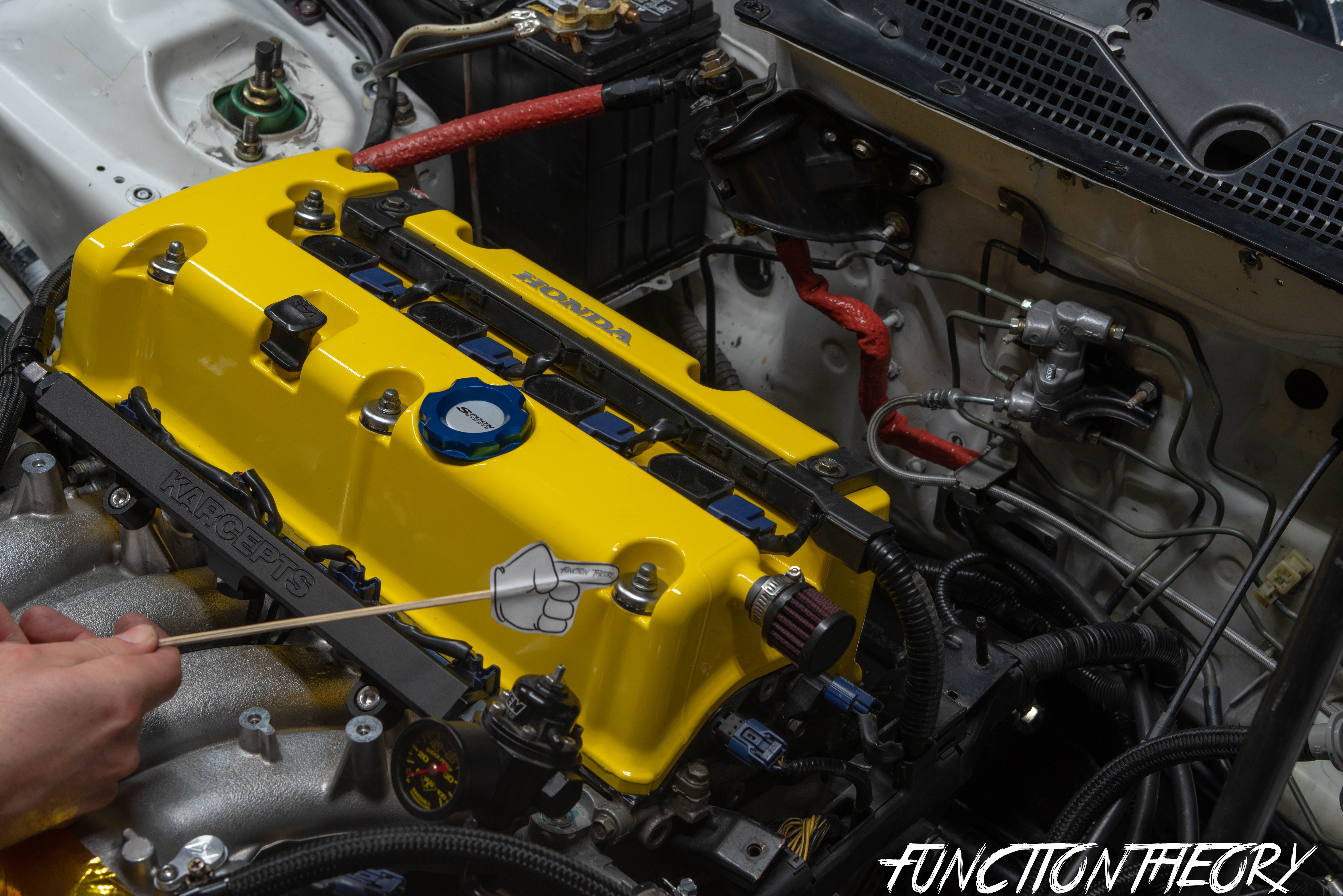
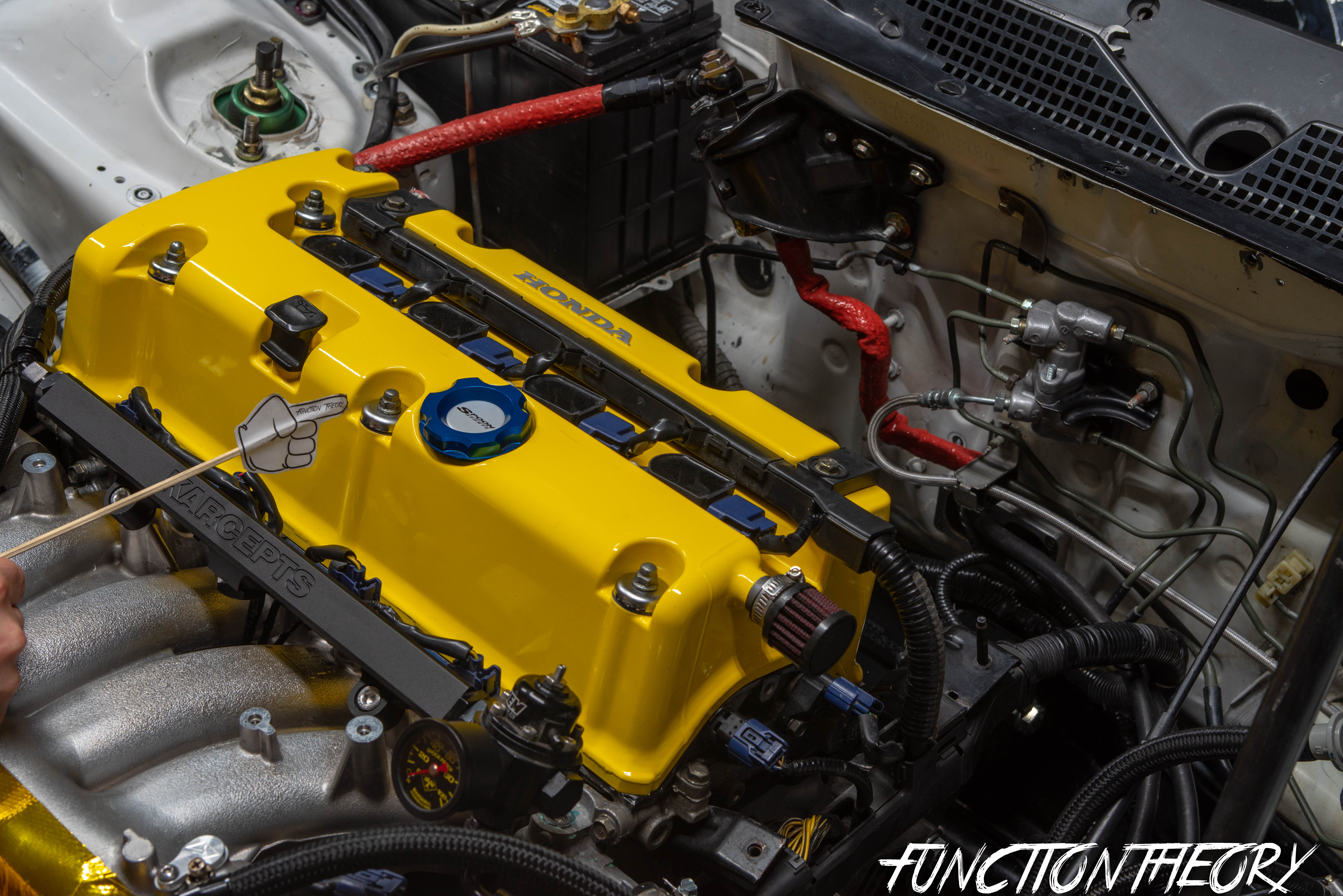
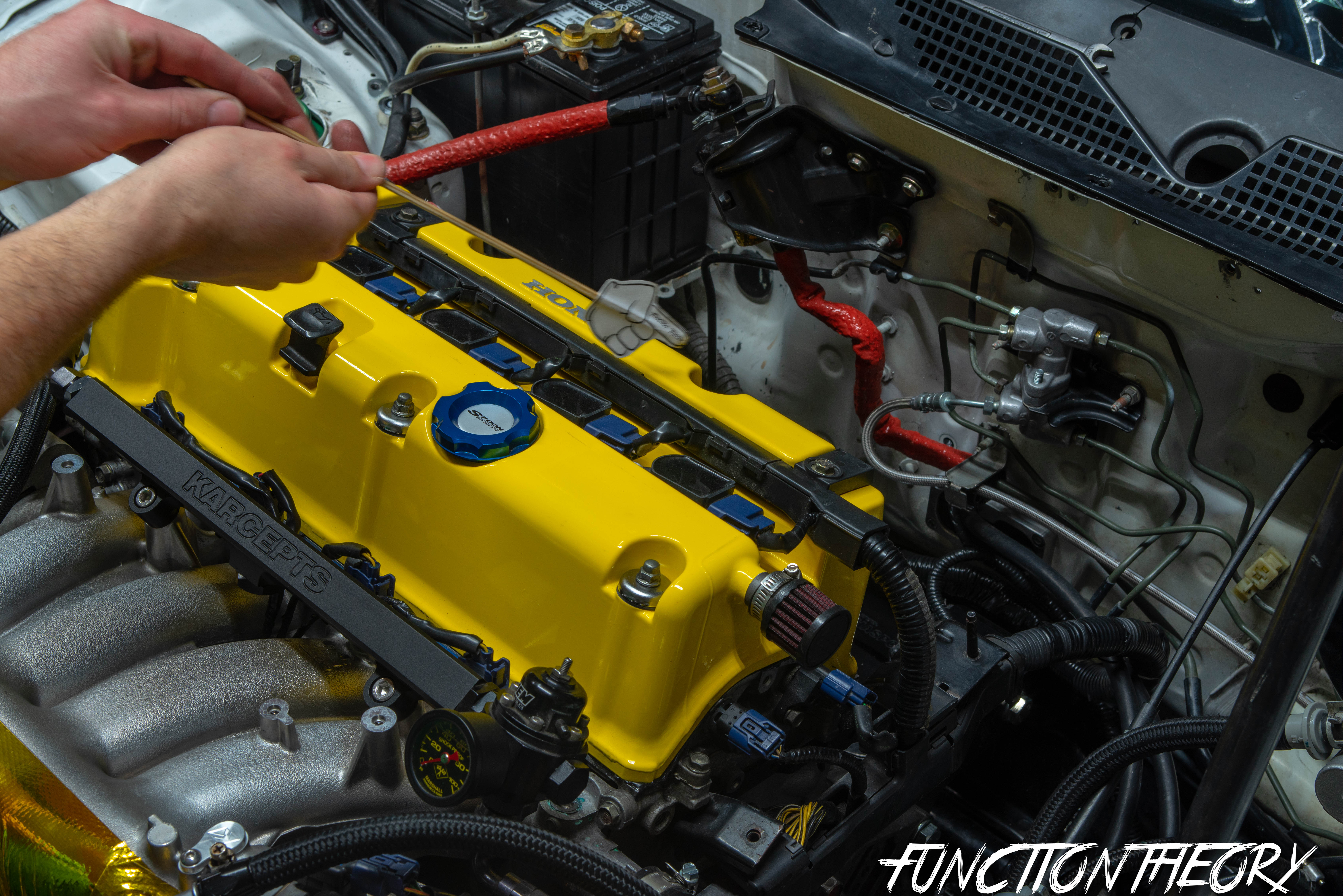
I use my hands like this…

I gently shift the valve cover back and forth to break the seal. You can also use a plastic scraper or an interior panel remover to lightly pry between the head and the valve cover if needed. Shifting the valve cover back and forth will help the grommets move up the studs, allowing the cover to shift more freely.
You’ll know when it’s loose enough to remove. I’ve tried to illustrate below how the valve cover shifts slightly front to back (hence the slightly out-of-focus photo).

The valve cover should now lift off easily. I don’t recommend replacing the spark plug hole gaskets, as they’re a pain to install and often end up getting damaged. You generally won’t need to replace them unless oil is pooling in the spark plug tubes.

Step 3:
A valve adjustment should be performed when the engine is COOL—ideally below 100 degrees Fahrenheit. The best time to do it is in the morning before you even start the car. As we know, heat causes metal to expand, which can throw off your valve lash measurements.
Additionally, letting the engine sit overnight allows much of the oil to drain out of the head, reducing the amount of oil that leaks when you remove the valve cover (though some leakage is inevitable no matter what).
The K-series engine (like most Honda engines) has a firing order of 1, 3, 4, 2. Cylinder #1 is located closest to the timing chain/gears, while cylinder #4 is closest to the transmission. Each cylinder has four valves—two exhaust and two intake—leading to a total of 16 valves.
To perform a valve adjustment, you must find Top Dead Center (TDC) for each cylinder, as only one cylinder can be at TDC at a time. I’ll show you how to ensure you’re correctly setting each cylinder to TDC.
There are timing marks on the gears, and the cam lobes will point in a specific direction. (Using a method like sticking something into the spark plug hole and watching it rise as you turn the crankshaft bolt can tell you when the piston is at the top, but that’s not necessarily TDC—it might not be on the compression stroke. Please avoid this method, as it could lead to incorrectly adjusted valves.)
Below is cylinder #1 at TDC

The arrow is pointed up, and there are lines on each timing gear, and they will be pointing towards each other.

Next, the cam lobes should point inward toward the spark plug tube, with the exhaust side pointing towards roughly the 2 o’clock position and the intake side pointing towards roughly the 10 o’clock position. Use the VTEC lobe as a reference, as it’s the easiest to spot (the largest middle lobe).

Now, move to cylinder #3 (following the firing order: 1, 3, 4, 2). Use your ratchet on the crank pulley and rotate it clockwise until the arrows on the cam gear have rotated 90 degrees and align like this.

Also, take note of the lines on the cam gears. The visible intake cam gear line points upwards, while the exhaust cam gear (which can’t be seen due to the shock tower blocking it) points downwards.
Remember, this is TDC for Cylinder #3.

Again, pay attention to the VTEC cam lobes, which point inward toward the spark plug tube—roughly 2 o’clock for the exhaust cam and 10 o’clock for the intake cam.
ow, let’s move to TDC on Cylinder #4 (following the firing order: 1, 3, 4, 2). Cylinder #4 is located closest to the transmission. Use your ratchet on the crank pulley and rotate it clockwise until the arrows have moved another 90 degrees, pointing downward.

ke note of the lines on the cam gear. The intake cam line points forward toward the radiator, while the exhaust cam line (which can’t be seen due to the shock tower) points backward toward the firewall.

The cam lobes for Cylinder #4 will be pointing in the same direction as the previous cylinders—toward the spark plug tube. The exhaust side will point around 2 o’clock, and the intake side around 10 o’clock.
he markings for the fourth and final cylinder, Cylinder #2, should look like this. Remember to use your ratchet on the crankshaft bolt and rotate it clockwise again until the arrow moves another 90 degrees, following this pattern.

Now, you’ll notice the line on the exhaust cam gear is on top, pointing upwards, while the line on the intake cam gear is the opposite, pointing downward (though it can’t be seen due to the paper pointer finger blocking it).


Now, let’s take another look at the cam lobes and see what they look like when Cylinder #2 is at TDC.

You guessed it—same as the other three cylinders. The VTEC lobes will be pointing inward toward the spark plug tube, with the exhaust side at roughly 2 o’clock and the intake side at 10 o’clock.
Now that you understand how to identify the markings that indicate which cylinder is at TDC, along with the firing order (1, 3, 4, 2), you’ve got a fail-proof method to ensure each cylinder is at TDC by checking the orientation of the cam lobes.
Go ahead and test yourself by rotating the crankshaft ratchet a few full rotations and seeing if you can determine which cylinder is at TDC. Keep in mind, the engine sits naturally at a lean angle, so use the engine itself as the reference point for the cam gear marks, not the car.
As long as the cam gear lines are exactly opposite in direction, and the cam lobes are pointing correctly at 2 o’clock and 10 o’clock, you can’t go wrong. Remember, the cam lobes will only align at these positions when the cylinder is truly at TDC.
Step 4:
Now that you know how to set each individual cylinder to TDC, I’ll walk you through the process of adjusting the valves. I won’t cover every single valve, but I’ll show you how to adjust a few as examples. You’ll be adjusting 4 valves per cylinder—2 intake and 2 exhaust.
The valve lash specs are as follows:
Intake: 0.21 – 0.25mm (0.008 – 0.010 in.)
Exhaust: 0.25 – 0.29mm (0.010 – 0.011 in.)
Again, note that this might vary depending on your specific K-series motor—please double-check your service manual. For my setup, I set the intake valves to 0.008 inches and the exhaust valves to 0.010 inches.
ome people suggest that if you can’t fit a 0.011-inch feeler gauge on the intake side or a 0.012-inch feeler gauge on the exhaust side, then that valve doesn’t need adjustment. However, I prefer to adjust every valve since I’ve already gone through the work of removing everything.
I run tighter clearances to ensure the valve opens that extra millisecond, allowing for maximum air and fuel intake, which improves combustion and maximizes power output.
It’s also a good opportunity to double-check all the adjustment nuts to ensure none are loose. When torquing down the lock nut after setting the clearance, be careful to tighten to only 14 ft-lbs. Over-tightening can cause the nut to snap relatively easily.
To adjust the valve, take the feeler gauge and slide it between the top of the valve spring/valve and the bottom of the rocker arm.

There should be some resistance or drag on the feeler gauge. If it slides in and out too easily, the clearance is too loose, and you’ll need to make an adjustment.

Seen above, I’m trying to show the movement of sliding the feeler gauge back and forth.

You’ll adjust using your jam nut valve adjustment tool. First, loosen the 10mm lock nut, then use the flathead screwdriver to turn clockwise to tighten or counterclockwise to loosen the gap.
The way I usually do it is: loosen the nut, then slowly turn the flathead while sliding the feeler gauge back and forth until you feel the desired drag. Keep the flathead steady (without rotating further) while tightening the lock nut. The feeler gauge should have noticeable resistance, but it shouldn’t be stuck or too difficult to slide in and out.
As shown in the pictures above, you’ll need to adjust the two intake valves (with specs ranging from 0.008 to 0.010 inches).
Remember, don’t over-tighten the lock nuts—the torque spec is 14 ft-lbs.


Next, adjust the two exhaust valves (with specs ranging from 0.010 to 0.011 inches).
Remember, don’t over-tighten the lock nuts—the torque spec is 14 ft-lbs.
Certainly, there’s no need to demonstrate the adjustment of every single valve, as that would be repetitive. I’ve already provided a clear visualization of each cylinder at TDC for your reference. Now, let me walk you through the precise steps to perform the valve adjustment, building on your understanding of setting each cylinder to TDC and the valve adjustment process.
- Set cylinder #1 to TDC, adjust the 2 intake valves for cylinder#1, and the 2 exhaust valves for cylinder #1
- Set cylinder #3 to TDC, adjust the 2 intake valves for cylinder #3, and the 2 exhaust valves for cylinder #3
- Set cylinder #4 to TDC, adjust the 2 intake valves for cylinder #4, and the 2 exhaust valves for cylinder #4
- Set cylinder #2 to TDC, adjust the 2 intake valves for cylinder #2, and the 2 exhaust valves for cylinder #2
Step 5:
Reassembling everything. Now that you’ve adjusted all 16 valves—4 per cylinder (2 exhaust and 2 intake)—I recommend going through a full cycle of each cylinder at TDC and using the feeler gauges to double-check that all clearances are within spec. Make sure the resistance on the feeler gauge feels consistent across all valves on each cylinder.
At this point, I also double-check to ensure all lock nuts are properly tightened. Loose nuts can cause issues once the engine is running, leading to potential heartbreak.
Take a clean rag and wipe away any oil and debris around the head where the valve cover sits. Pro tip: Ensure the surface is as clean as possible to allow the valve cover gasket to create a proper seal, preventing any potential oil leaks.

Watch closely as I expertly take my index finger, wrapped in the towel, and make a precise sweep around the entire head, paying extra attention to the header side. It’s no secret that this is typically where the most oil escapes when you remove the valve cover, but with this technique, I ensure every trace is efficiently dealt with.

You also want to make sure you clean all the old Hondabond/RTV silicone off the area where the valve cover gasket meets the head.

You can see above that there is a small piece of dried Hondabond that needs to be picked off. Make sure it doesn’t fall into the head!
At this point, it’s entirely up to you whether to use a new valve cover gasket or not. As I mentioned earlier, mine is fairly new, so I’m not replacing it. Eric’s is over 5 years old, and I’m not replacing his either. It’s not common for the valve cover gasket itself to leak. If you’re applying new Hondabond/RTV silicone sealant, there’s typically no need to replace the valve cover gasket unless its very old, hard, and dried out.
If you do decide to replace the gasket, DO NOT get one from AutoZone, Pep Boys, O’Reilly’s, etc., as they tend to leak over time. Only use the OEM gasket from Honda. The part number from Acura is: 12030-PNC-000, which includes the new valve cover grommets and washers. If you’re searching for it, it’s listed as GASKET SET, HEAD COVER.
If you decide to reuse the valve cover gasket (like I did), make sure to carefully remove all the old Hondabond/RTV silicone sealant to ensure a proper seal between the valve cover and the head. When reinstalling the gasket onto the valve cover, it can only be installed one way, so pay close attention to ensure proper alignment!

Above, you can see the fresh Hondabond (grey silicone) I applied. Notice that it only needs to be applied in those four key areas—just a small amount will do. DO NOT apply Hondabond around the entire perimeter. Additionally, ensure your “old” gasket is clean and dry, just like mine. The surface where the valve cover sits on the head should also be completely dry, as well as the valve cover gasket itself (except for the four areas with Hondabond). This will help ensure a proper and leak-free seal.

You will want to clean the oil off these as best as possible, to ensure the best seal.
Now, go ahead and carefully set the valve cover back onto the head, ensuring no lines or wires are pinched between the valve cover and the head. Once in place, install the rubber grommets onto all six holes.

Make sure each rubber grommet fits fully into the valve cover. The centering portion of the grommet should fully seat into the valve cover, as shown above. Double-check that all six grommets are properly seated before starting to tighten the valve cover. Ensuring proper seating prevents any part of the grommet from being pinched, which could lead to oil leaks. Once confirmed, go ahead and place the metal washers onto each of the six bolts. Thread the 6 nuts onto the bolts by hand to get them started. Be cautious, as these can strip easily, which could prevent achieving the correct torque and potentially cause oil leaks.
Using a ratchet, tighten the six nuts in a star pattern, following the same procedure as tightening lug nuts. Perform the tightening in a 3-step process: first, snug them down evenly, then apply a bit more torque, and finally, tighten to the final torque spec of 7.2 ft-lbs.
- Reinstall the spark plugs.
- Bolt the ground back onto the valve cover.
- Install the valve cover breather hose (if your vehicle has one) and the oil dipstick. Be sure to wipe the dipstick clean before reinstalling it.
- Install the coil packs by seating them over the spark plugs and reconnecting the wiring harness. Tighten the 10mm bolts for the coil packs to 8.7 ft./lbs.
- Install the ignition coil cover using the four 10mm bolts. Torque these bolts to 8.7 ft./lbs.
- Finally, remove the ratchet from the crank pulley and reinstall the wheel.
And If you have a stock car
- Install the 10mm bolts holding the cruise control cable and power steering pump bracket.
- Install the intake manifold cover using its two 10mm bolts.
DON’T FORGET TO REMOVE THE RATCHET ON THE CRANK PULLEY BEFORE STARTING THE CAR!!!!!!!!!!!!
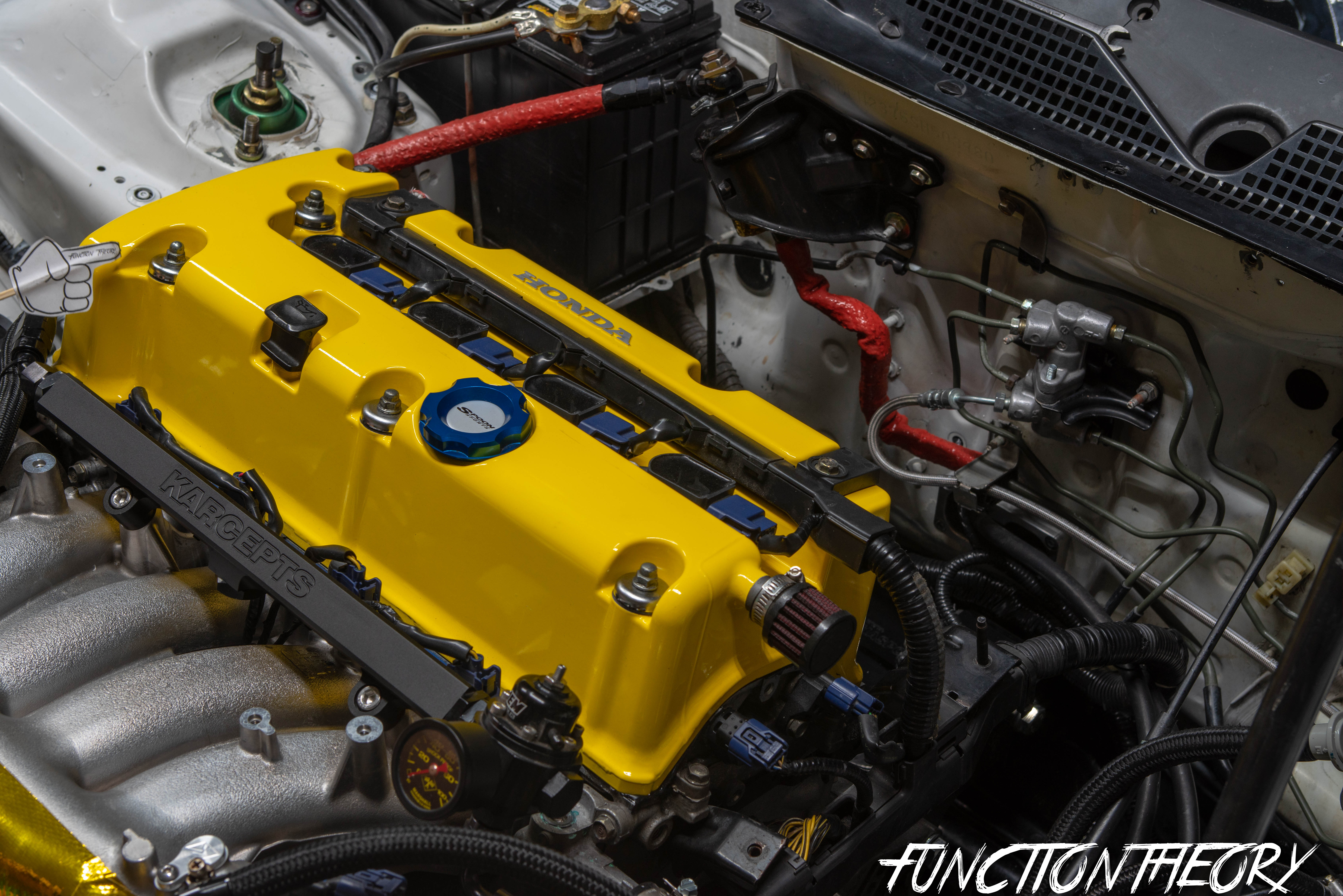
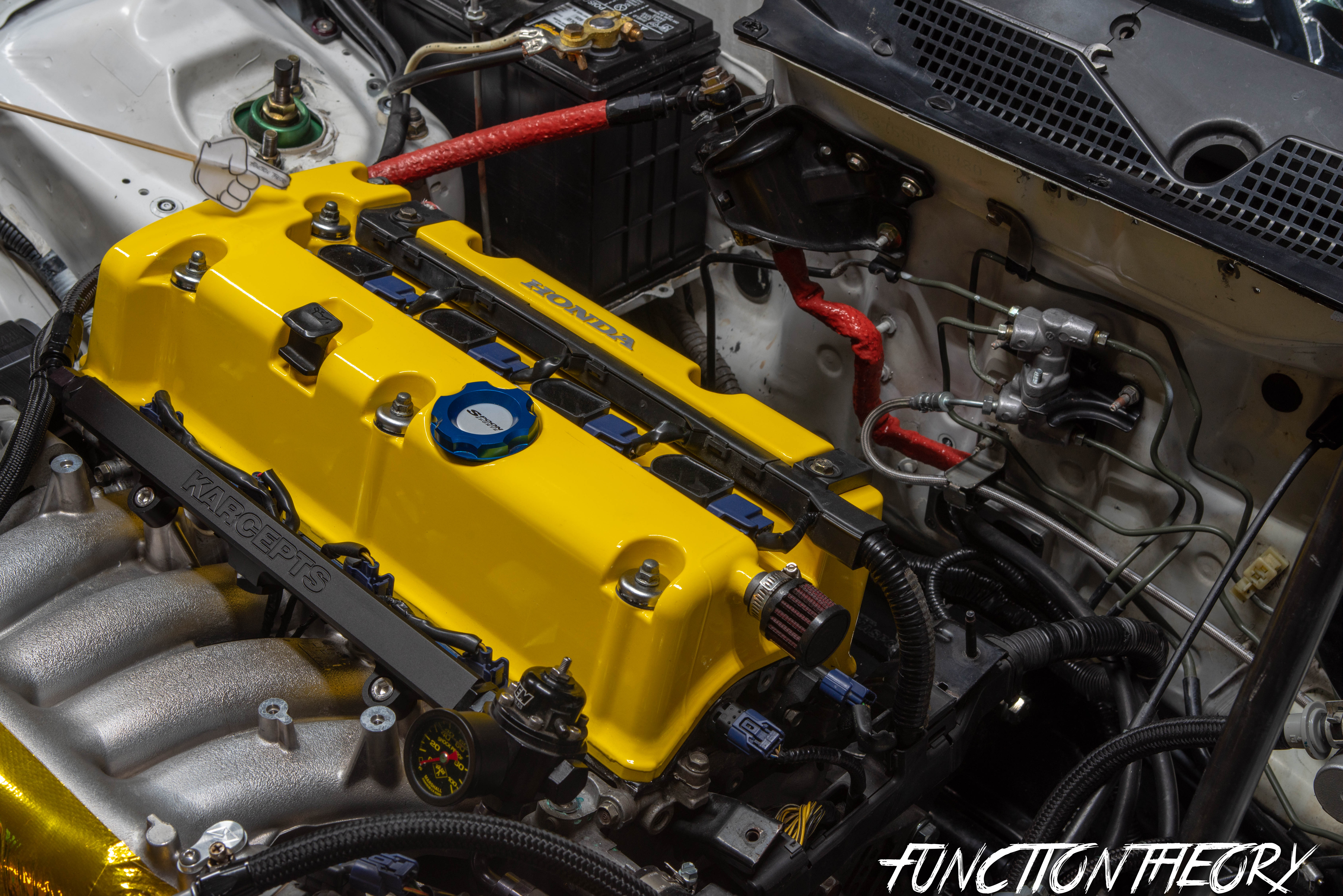
Here is how everything looks all back together


I hope this helps boost your confidence in adjusting your own valves. Get out into the garage this weekend and show your car some love! As always, please like, comment, and share. If you have any questions, feel free to reach out—I’m here to help! You can contact me via email at Billy@FunctionTheory.com, on Instagram @FunctionTheory, or simply leave a comment below.
And lastly if you want to check out the S2000 (F20C) valve adjustment DIY click the link below.
560,413 hits
This is such an amazing write up of the valve adjustment procedure! I’m surprised nobody has commented to give thanks at least! Ima be the first! Thanks for the well written info, will be adjusting my valves on my k20z3 within the next week now that I have this to reference
Thank you so much! I’m glad you found this useful, and I appreciate you taking the time to comment I love it when people interact. It’s nice to hear that what I’m doing is helpful
Hello!, i have a doubt with my k24a3 when doing this work, do you think that the minimum clearance is the most correct? I have seen other people doing it like this but…
I did 0.25 on intake and 0.30 on exhaust before reading enough, resulting on a loud sound as they are too loose, at least on the exhaust ones.
Now i am going to lower the valve clearance, but taking in mind that intake valve clearance tends to go up (in which case the valves would be OK despite of getting more clearance until 0.25), and exhaust valve clearance tends to go down, wouldn’t it be the best to adjust exhaust valves to 0.28 instead of 0.25? I know the clearance that gives the most perfomance is the closest to the minimum, but won’t them get out of range resulting in a “dangerous” situation for the before the next adjust(120k)?
Waiting for you reply.
Thanks!
Hi Dave, thanks for reaching out. after a quick search on google i was able to find these specs.
The specification is:
Int .008-.010; Exh .011-.013.
now please keep in mind this is only what I came across, and might not actually be correct since this is for a USDM motor. but the specs you mentioned above seem to be too loose for any Honda. Usually the valve lash tolerances are much tighter, which is why I believe the ones i’ve supplied are more correct. Please also note that there are usually two ways to measure valve lash. millimeters (mm) or inches (in) please make sure you are not mixing up the two.
Thank you so much
The information you provide is quite clear that provides security and excitement to perform the adjustment of the valves of my car
Thank you very much again and God bless you and everyone
Yes, I mentioned valve las instituciones mm. I wanted to say that I adjusted the clearance 0.25mm on intake(0.010 inches) and 0.30mm (0.012 inches) on exhaust.
My question is about which clearance would be the best between the allowed range for both valves, as 0.008inches clearance on intake is fine in my opinion as it usually tends to go up When the engine runs kms and the time passes by. But when we talk about the exhaust valves, if we adjust them to the minimum clearance allowed which is 0.010 inches, wouldn’t we compromise the security of valves when they start to be more tightened(when the valves become loose they sound but they won’t be hurt)? Because the exhaust Valve clearance tends to tightend.
The correct valve clearance for my k24a3 is 0.008-0.010 intake/ 0.010-0.012 on exhaust.
Thanks.
Honestly in my opinion anything withing the specs should be fine regardless of the miles (KM) on the motor. If you have them adjusted within spec and you are still hearing a noise, its possible that the timing chain tensioner may be causing the noise.
Please keep in mind it’s incredibly difficult to diagnose things over the internet. It would be much easier for me to give you better guidance if I could see/hear it in person, so the best thing i can do I just give you some basic guidance. Sorry i cant be of more help.
Allright, I just don’t wanna have any diagnose, the only thing I wanna ask or debate with you and other experts, is that if you adjust your exhaust clearance at the lower point allowed, when it passes 50 or 80.000kms your valves will be at less than that clearance because exhaust valves tend to get more tight. I could see thst when I inpected the valves st the first time, intake tends to get bigger clearance and exhaust the oppositte.
See you, nice post!!
i feel like this is all down to how well the engine is taken care of. as long as you’re within the spec’s then making it on the loser side (within spec) shouldn’t cause any issues. Thanks for reaching out.
Thank you so much! Simple put and detailed. This will definitely be my reference guide as this will be my 1st time doing a k series valve lash adjustment. I have a question, I have a K24A2 and I am running the valve seat, dual valve springs, valve retainer from a K20A Type R on both exhaust and intake side, would the specs still be 0.008/0.0010 ?
Hi! I’m so happy you liked the article. As for what lash to set yours to, I wouldn’t set it to a k20 spec because it’s still a k24 (rod length, valve size, cam specs) any other questions don’t hesitate to reach out